Robotics and AI  ›  AGV Programme

A delivery robot, built from nothing.

The Techvein AGV is an autonomous ground vehicle designed, fabricated, wired and programmed entirely in‑house — chassis, steering, power electronics, custom control board, remote and software. It carries a parcel to a marked waypoint on its own, sees in every direction, and logs what it finds along the way.

<3 cmLateral drift over a 5 m run, under payload
<5%Path deviation on commanded circles
90°Turns completed without overshoot
In‑house R&D The Techvein AGV — autonomous delivery vehicle AGV — Coming to life

Why it exists

We set out to build the hardest thing we could.

The AGV began in February 2026 as an R&D exercise: could our own engineers take a robotics problem normally reserved for university labs and industry — autonomous indoor navigation with a real payload — and solve it end to end? The answer turned into a working vehicle, and the vehicle turned into the platform our robotics teaching is now built on. Everything on it was made or specified by Techvein engineers: the welded steel frame, the steering geometry, the power distribution, the hand-laid control board, the 3D‑printed remote and every line of firmware.

The machine

What it actually does

A two‑tier brain: a Raspberry Pi 5 runs vision and mission logic, while a Teensy 4.1 holds real‑time control of motors, steering and sensors.

Compute
Teensy 4.1 + Raspberry Pi 5
Vision
4 cameras · 360° · AprilTag
Steering
Ackermann geometry · PID
Electronics
Custom all‑in‑one PCB, rev 3
🧭

Autonomous navigation

Drives an indoor route on its own, with a tele‑operation override and kill switch always available.

👁️

360° AprilTag vision

Four cameras feed an OpenCV pipeline on the Pi, decoding fiducial tags to locate itself and stop on the mark.

🛑

Obstacle avoidance

Ultrasonic sensors on both flanks trigger avoidance before anything is touched.

📦

Parcel delivery

Validated carrying 0, 0.5 and 1.0 kg payloads without losing its line.

📊

Data collection

Logs telemetry and environmental readings to onboard storage as it moves.

🧠

Sensor fusion & data collection

IMU and wheel‑encoder odometry fused through an Extended Kalman Filter — the current phase of work.

Two generations

v2 proved it. v3 is making it precise.

The first complete vehicle worked — and showed us exactly what to rebuild.

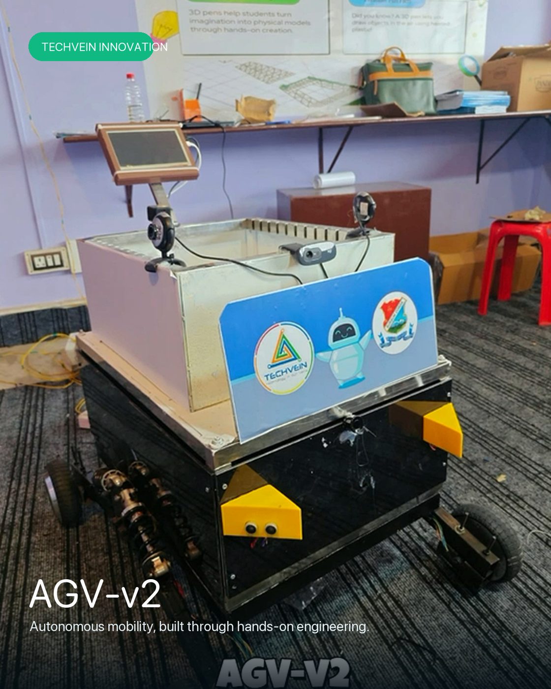
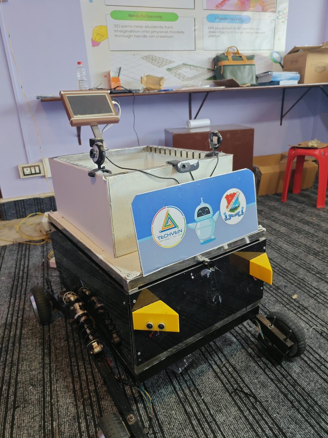
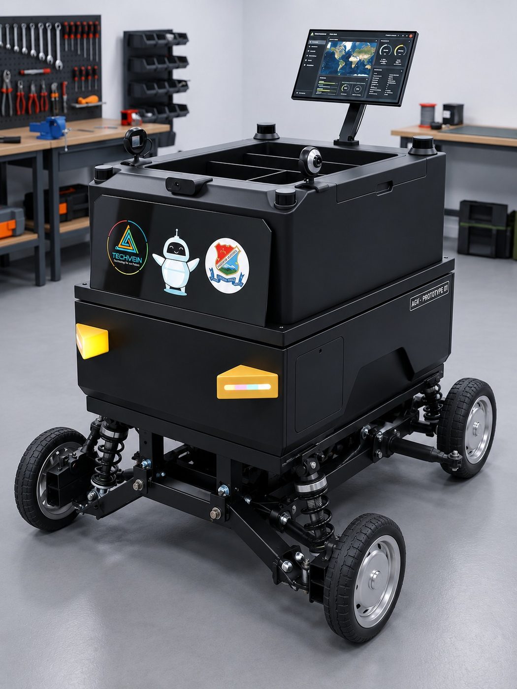
Techvein AGV v2, complete with cargo enclosure and display
✓ Complete

AGV‑v2

The first fully enclosed vehicle: cargo body, onboard display, four‑camera vision and the first custom PCB. It passed its integration trials — and hit a wall on tight turns.

  • Raspberry Pi 5 and Teensy 4.1 bridged over UART
  • Four‑camera AprilTag vision, bilateral ultrasonics
  • First all‑in‑one PCB, replacing fragile breadboard wiring
  • Limitation found: differential drive could not execute a clean 90° turn
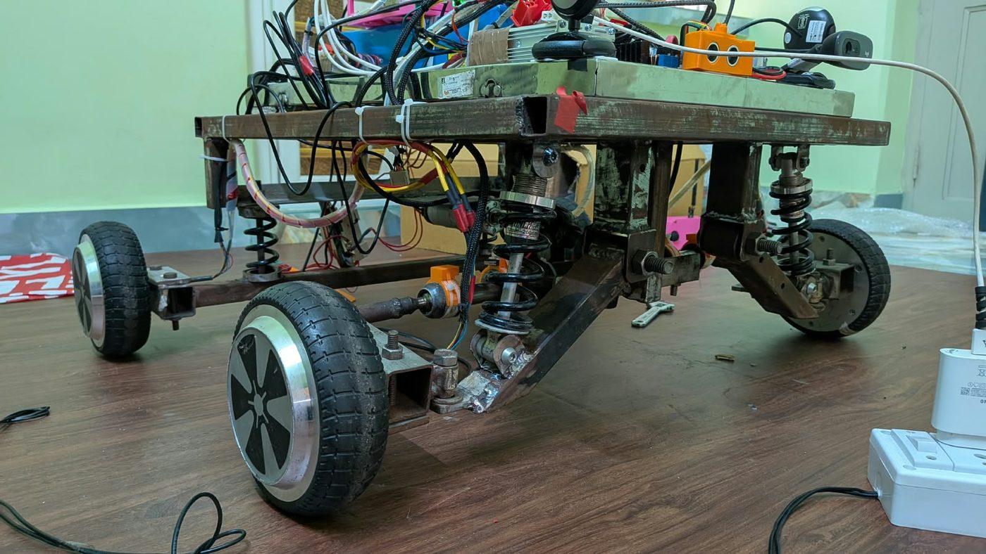
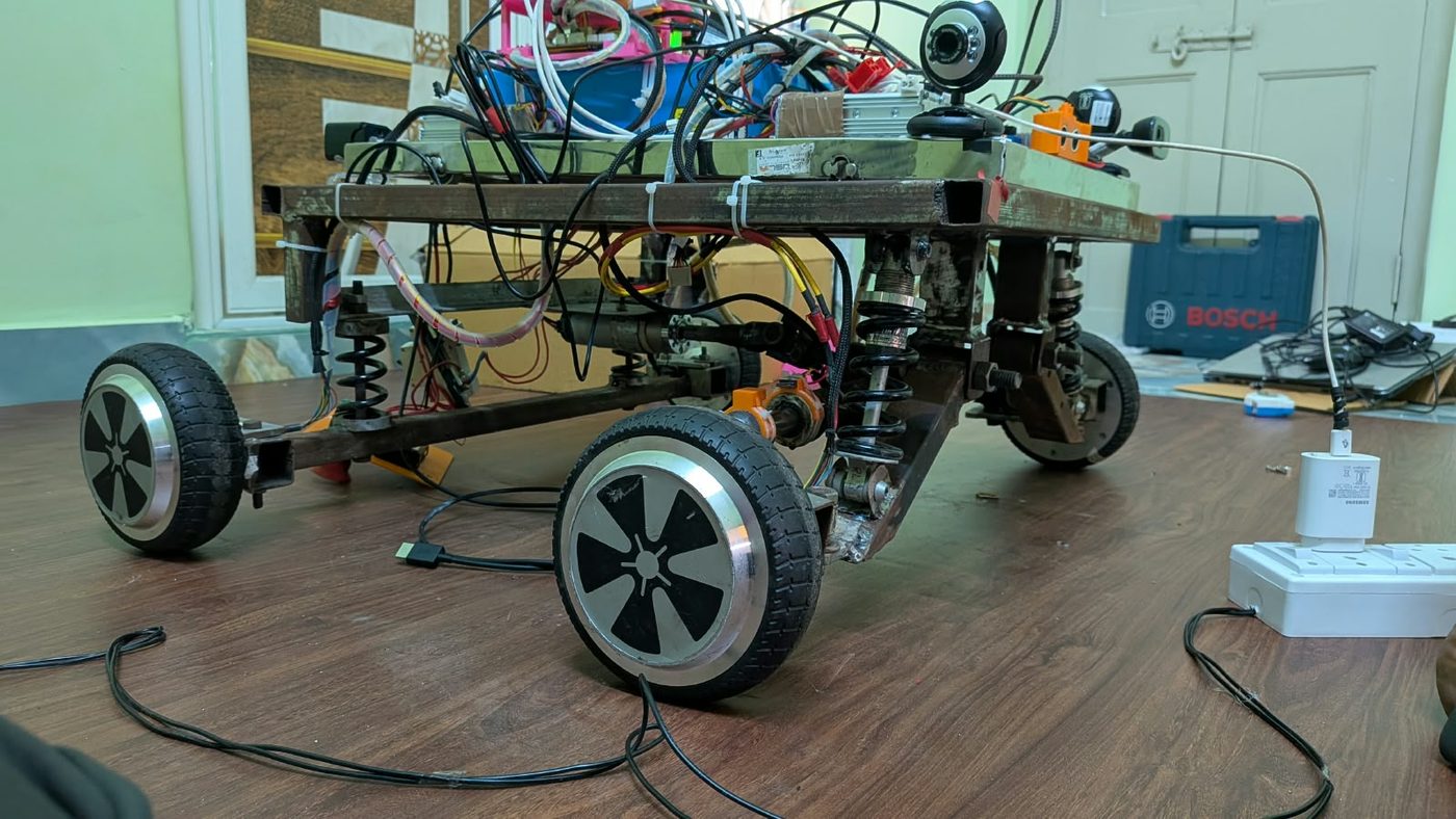
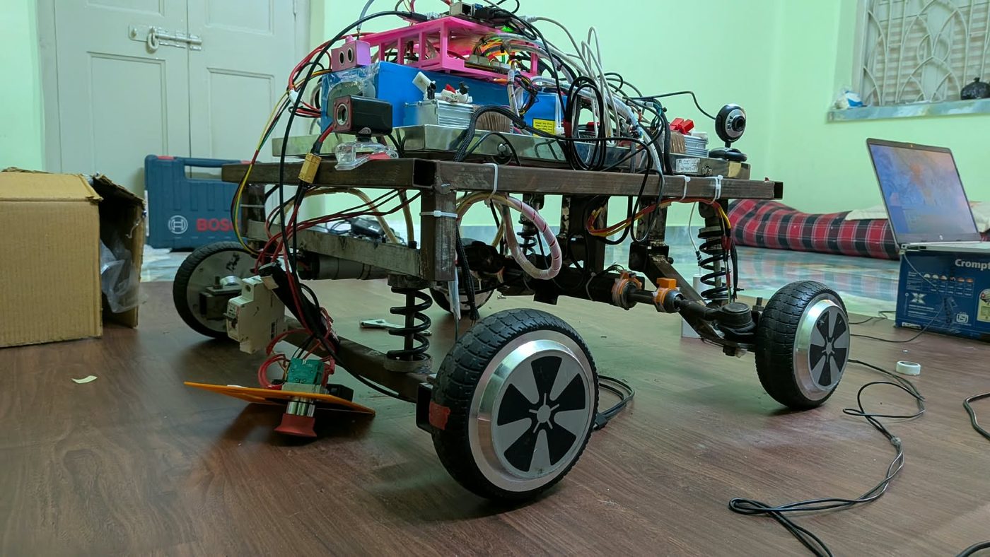
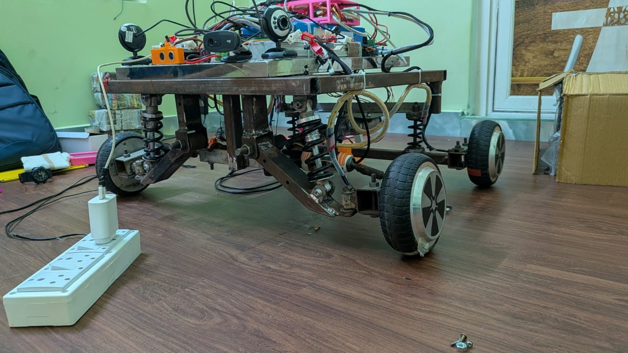
Techvein AGV v3 rolling chassis with Ackermann steering
◐ Current platform

AGV‑v3

A ground‑up mechanical revision built to fix that one limitation — and it did. New steering, new suspension, a third‑revision board and a purpose‑built remote.

  • Ackermann steering, chosen over four‑wheel steering after prototyping both
  • Independent coil‑over suspension protecting sensors from vibration
  • PCB rev 3 — lower signal noise, steering motor integrated
  • Servo‑actuated mechanical brake for shorter emergency stops
The build

Made, not assembled

Five stages from bare stock to a vehicle that drives itself.

Stage 01

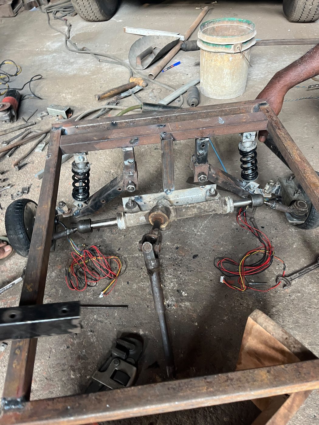
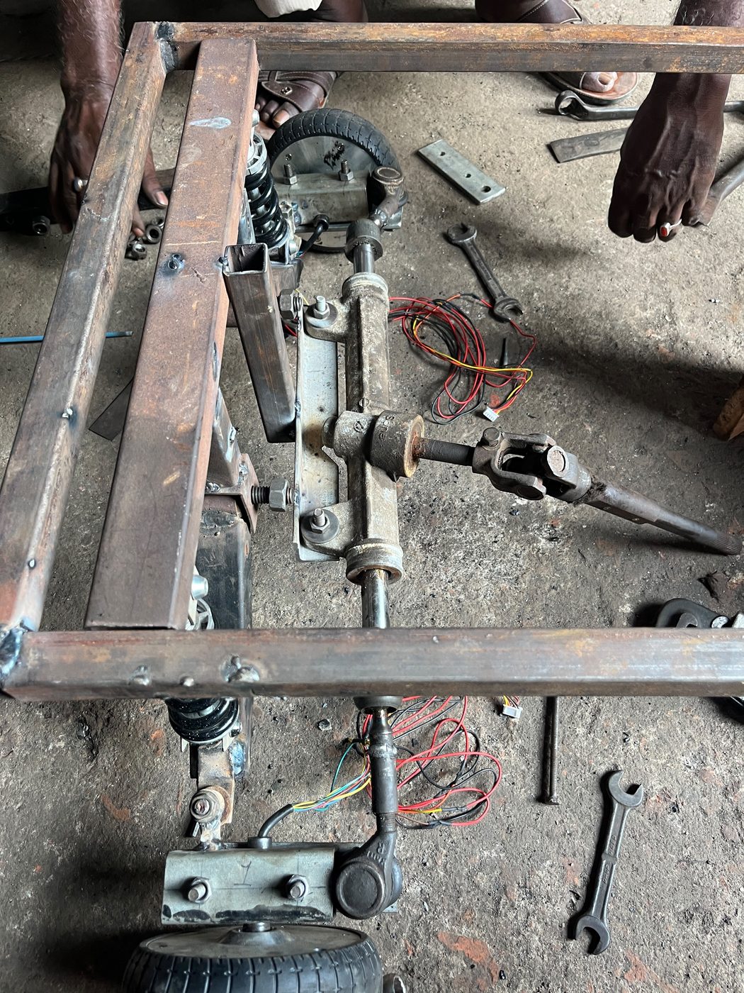
Frame and running gear

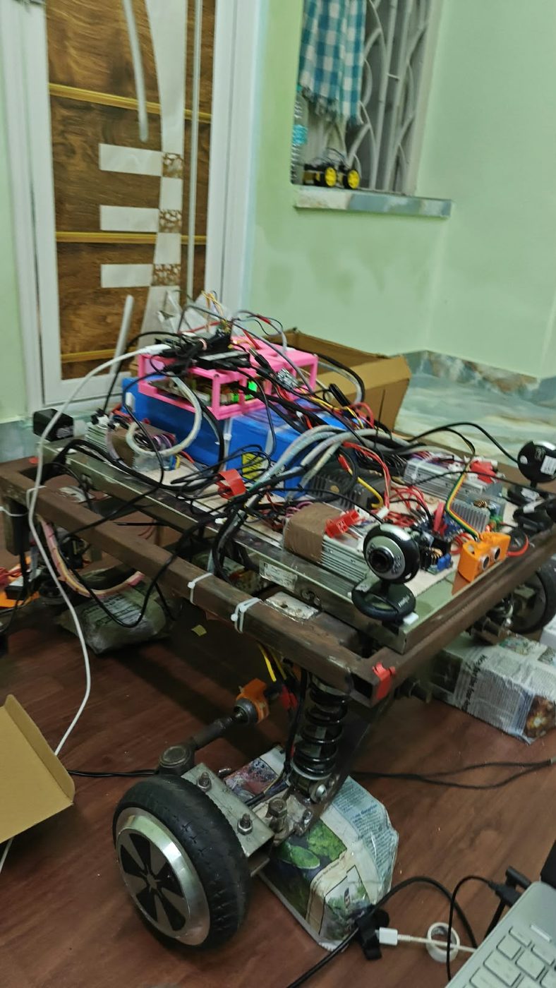
The chassis was cut, welded and drilled in our own workshop. Steering knuckles, tie rods, hubs and coil‑over dampers were fitted and aligned by hand, then the geometry was checked and re‑checked until the wheels tracked true.

  • Welded steel box‑section frame, built in‑house
  • Ackermann steering linkage with adjustable tie rods
  • Independent coil‑over suspension at each corner
  • Wheel alignment corrected after the first trial run exposed drift
AGV steel frame under fabrication
Frame fabrication — cutting and fitting the box section
AGV steering assembly close-up
Steering knuckle and tie rod assembly
Completed AGV rolling chassis
Rolling chassis complete, suspension loaded
Stage 02

Drive and steering

Brushless drive motors, controllers and the steering actuator were mounted to the finished frame. Turn‑angle commands were then swept at 10°, 30°, 45°, 60° and 90° to build a calibration table mapping software angles to real wheel positions, with a PID loop tuned until the oscillation disappeared.

  • Brushless drive with current‑limiting and inrush protection
  • Steering calibration swept and tabulated across five angles
  • PID loop tuned to a clean, non‑oscillating 90° turn
  • Servo‑operated mechanical brake designed and fitted
AGV suspension at ride height
Ride height and suspension travel under load
AGV drive motors mounted
Drive motor and controller mounting
AGV sensor deck
Sensor deck taking shape above the frame
Stage 03

The control board

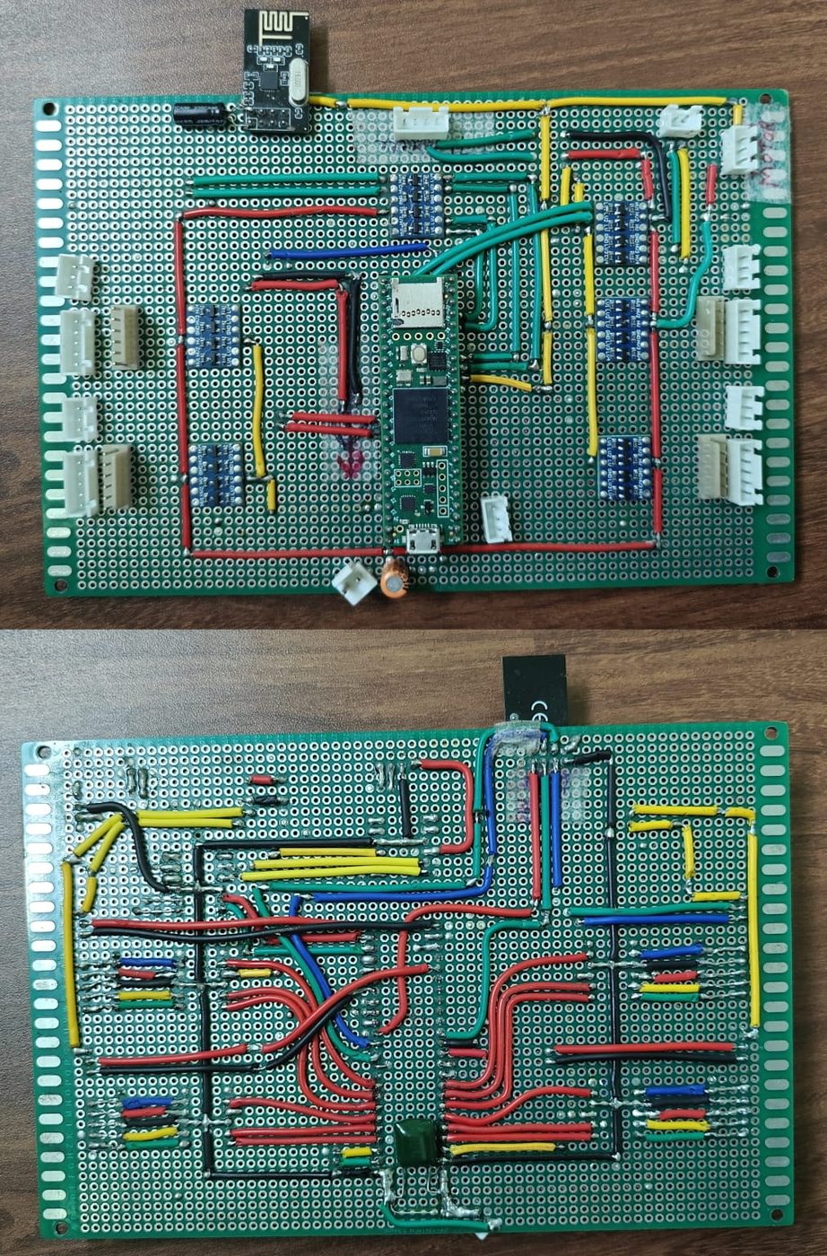
The vehicle originally ran on breadboard wiring, and the voltage instability that came with it. Our engineers laid out a single all‑in‑one board carrying every power rail, regulator, logic interface and sensor connector — then revised it twice more, cutting signal noise and folding in the new steering motor.

  • All power rails, regulators and logic on one hand‑laid board
  • Teensy 4.1 with nRF‑class radio for the remote link
  • Three revisions between April and May 2026
  • CAN bus was trialled for the inter‑board link and rolled back to UART, which proved sufficient
Custom AGV control PCB, both sides
PCB rev 3 — front and reverse, hand‑laid and soldered
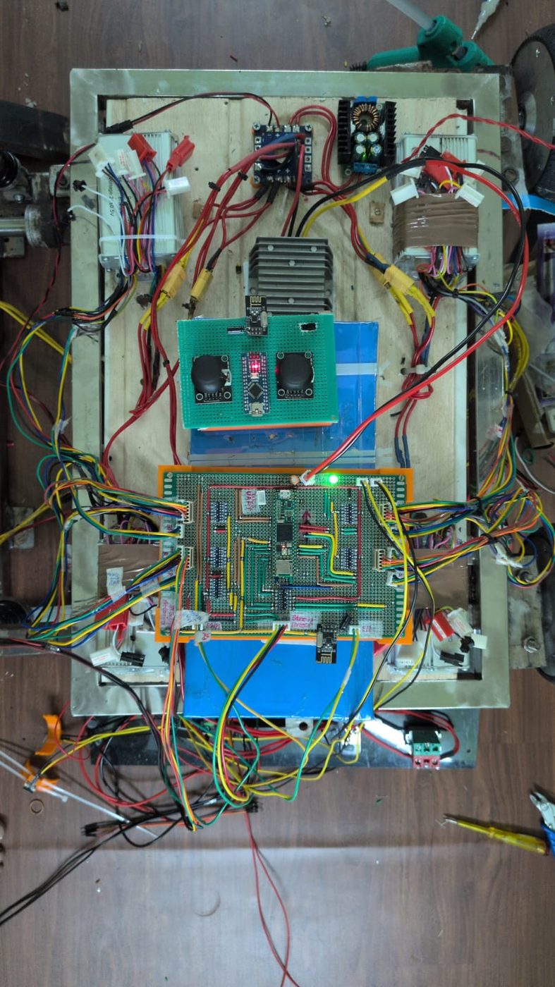
AGV control board installed
Board mounted and wired into the vehicle loom
AGV electronics on the bench
Bench integration — remote and main board live
Stage 04

A remote of our own

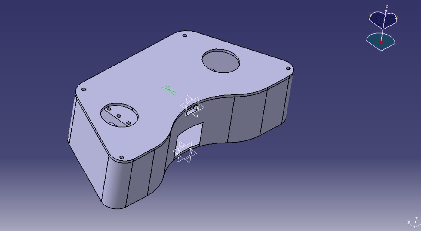
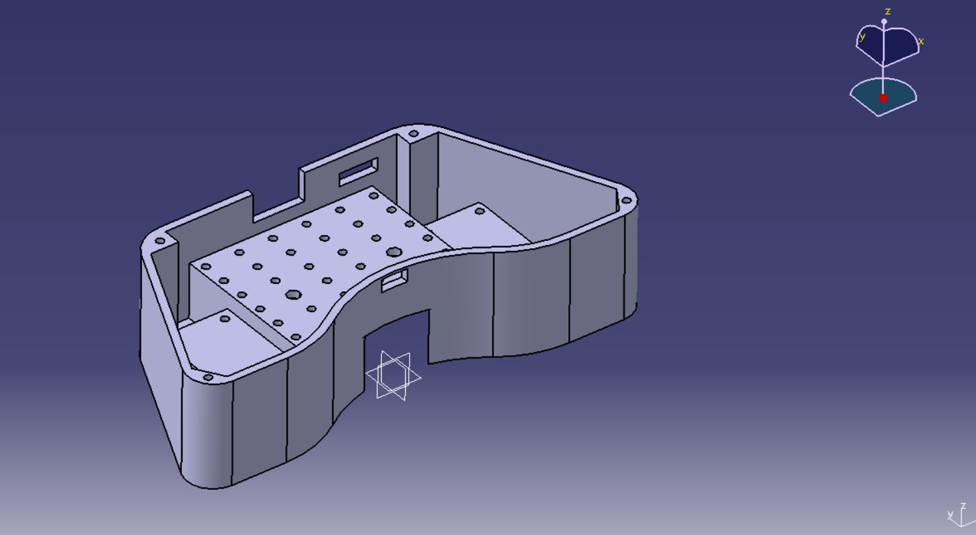
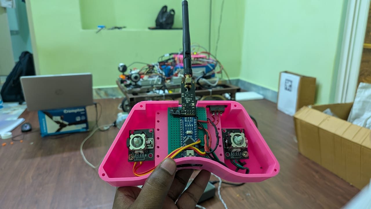
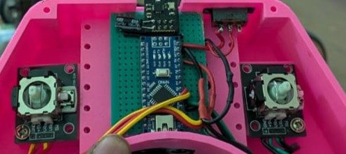
Rather than adapt an off‑the‑shelf transmitter, the team modelled a two‑stick controller in CATIA, printed the shell, and built the electronics into it — an Arduino‑class board, dual analogue joysticks and a radio link straight to the vehicle. It is the manual override used to prove the drivetrain before any autonomy is switched on.

  • Enclosure modelled in CATIA V5 — top shell and internal mounting base
  • 3D printed, with board standoffs designed into the part
  • Dual analogue joysticks: throttle and steering
  • Doubles as the safety override during autonomous testing
CAD model of the AGV remote controller shell
CATIA model — outer shell
CAD model of the remote controller base
CATIA model — internal mounting base
Assembled AGV remote controller
Printed shell with joysticks and board fitted
Stage 05

Body, power and vision

The v2 vehicle received its cargo enclosure, battery and power distribution, onboard display and the four‑camera vision ring. Shock absorbers were added specifically to keep vibration off the cameras and sensor boards while the vehicle is moving.

  • Lithium pack with distribution and step‑down regulation
  • Four cameras positioned for full 360° coverage
  • Onboard display for status and mission feedback
  • Vibration damping added to protect the sensor stack
Techvein AGV v2 complete vehicle
AGV‑v2 complete, in Techvein livery
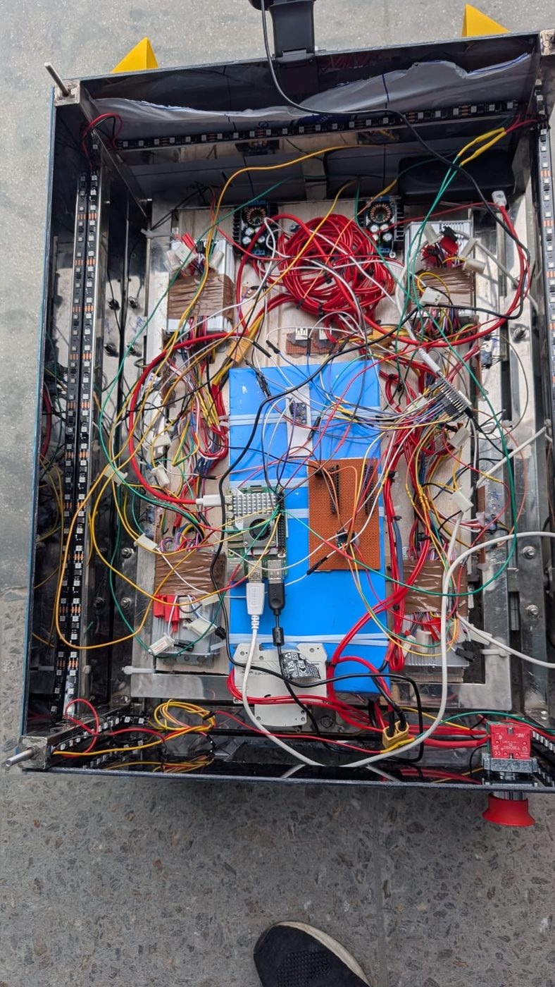
AGV electronics bay interior
Power and electronics bay inside the cargo body
Remote controller internal board
Remote internals — joysticks and radio
Test bench

Footage from the workshop floor

Unedited clips from the validation runs. Nothing staged — this is the vehicle being proven.

Working principleFour‑camera AprilTag detection driving the vehicle's response
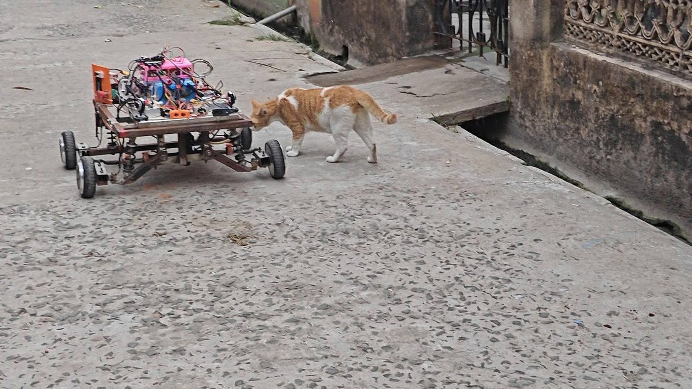
Full movement testAGV‑v3 driving under its own power
Rolling chassisWalk-around of the assembled platform
Steering testAckermann linkage articulating under load
Wheel rotationDrive-wheel response from the bench
Tele-operationRemote input, live serial telemetry
Control boardThird-revision all-in-one PCB
Programme status

Five phases, honestly reported

Phases 1 to 3 are complete and validated. Phase 4 is live work; Phase 5 is ahead of us.

Phase 1

Hardware & control

Core controller, drivetrain, actuator mapping and tele‑op override.

✓ Complete
Phase 2

Integration & vision

Raspberry Pi 5, four‑camera AprilTag, first custom PCB, trial runs.

✓ Complete
Phase 3

Steering & algorithms

Ackermann rebuild, PID tuning, circle and straight‑line validation.

✓ Complete
Phase 4

Sensor fusion & data collection

9‑DOF IMU, wheel encoders, EKF and a 10 Hz telemetry pipeline.

◐ In progress
Phase 5

Mission & deployment

Full‑scale mission runs, battery and thermal profiling, documentation.

○ Ahead
<3 cmLateral deviation over a 5 m straight run, tested at 0, 0.5 and 1.0 kg payloads
<5%Deviation on commanded 0.5 m and 1.0 m radius circles, loaded and unloaded
90°Turns completed with no overshoot or wobble after PID tuning
Behind the programme

Who leads this work

Mr. Nandan Singh, Founder and Chief Executive Officer
Founder & Chief Executive Officer

Mr. Nandan Singh

The AGV exists because Techvein's founder backed it as a research commitment rather than a commercial one — the conviction that a company teaching robotics should be able to build at the hardest level itself. It is also why the vehicle was kept in‑house rather than handed on.

Read his full profile →
Mr. Amit Dadhich, Chief Managing Officer
Chief Managing Officer

Mr. Amit Dadhich

Techvein's Chief Managing Officer has driven the programme alongside the founder — carrying it from the first cut of steel through every revision of the chassis, the board and the software to the vehicle running today.

Read his full profile →
R&D contributors to the AGV programme
  • Dr. Saptarshi Jana
  • Mr. Bairi Bhaskar Gond
  • Mr. Saurabh Chaturvedi
  • Mr. Nikhil Kumar
  • Mr. Rishabh Rathaur
  • Mr. Ravi Kumar
  • Mr. Mohit Kumar
  • Mr. Amir Khan
  • Mr. Suraj Sinde
  • …and the entire Techvein team

Every revision of this vehicle carries the work of people across the company — engineering, workshop, procurement and operations alike.

Bring it to your school

This is the standard behind our robotics labs

The engineering discipline that built the AGV is the same discipline we bring to a Grade 1–12 robotics and AI programme.

AGV Programme